|
WebCam System
The GV-System has a built in web server which is able to deliver streaming live and recorded video over the
Internet. This function is called the WebCam System, which allows users from anywhere in the world to
monitor their GV-System by using PCs or mobile devices via Internet access.
7.1 WebCam Setup
The Webcam system basically run within the Internet, there is no additional hardware or software required as long as your PC has Internet browser and Internet access.
System Requirement
| OS: |
Win 98SE, ME, 2000, XP |
| Web Browser
|
IE6.0 / Netscape Navigator |
| CPU: |
Pentium 500 (minimum) |
| Memory: |
128 MB RAM |
| Hard Disk: |
20 GB (minimum) |
| VGA: |
NVIDIA GeForce II 32MB at 800 x 600 resolution (minimum) |
| Network: |
TCP/IP |
| Connection Limit: |
Win98: up to 45 client login simultaneously.
Win2000:
256MB RAM = up to 132 channels simultaneously
512MB RAM = up to 145 channels simultaneously
728MB RAM = up to 174 channels simultaneously
1GB RAM = up to 178 channels simultaneously |
| DirectX: |
Client must have Direct X 8.0 or greater. |
Note: If the client is
on Windows XP or Windows Server 2003 platform, please surf to http://java.sun.com/getjava/ and download the JVM, Java Virtual Machine, in order to enable Jpeg View of the Webcam system.
WebCam Server Setup - Video
1. Click [Network] button from the GV-System main screen, enable "WebCam Server" from the menu and the following dialog box will appear.
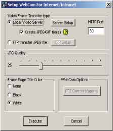
2. Select [Local Video Server] then click [Server Setup] button and the following dialog box will appear.
3. In the drop down list select the network adapter for WebCam System. The system will automatically detect the IP address of your PC and display it in the column below.
4. Enter the port number for [Command Port] and [Video Data Port]. The Command port default is 4550 and Data port default is 5550.
5. Enable [Assign GateWay IP Address] if your GV-System is connected to a private LAN where router is installed. Click [Auto Find] button and the system will automatically detect the IP address of your gateway computer.
Note:
If your GV-System is connected within a private network and the network's gateway computer is using a dynamic IP, then we do not recommend using WebCam's [Auto Find] function. We recommend that you register a DNS for your gateway computer.Instead of using IP address in GateWay IP Address column, input the gateway computer's DNS (i.e. geovision.no-ip.com).
WebCam Bandwidth Control Setup
Click on the [Video] tab in the "Server Setup" dialog box to access WebCam Bandwidth Control Setup. This setup allows you to specify how many WebCam and WebCam RPB user are allowed to access to your GV-System at one time. It also allows you to control the network bandwidth for WebCam RPB software.
WebCam Server Setup - Audio
Click on the [Audio] tab in the "Server Setup" dialog box to access WebCam Audio Setup.
Every server can send and receive audio from a maximum of 20 clients. ADPCM and G.723.1
are the two formats used by GV system to transmitting the audio signal. ADPCM requires 4KBps
(4,000Bps) of transmission speed, while G.723.1 only requires 600Bps of bandwidth.
Note:
When using server to client, you have to input audio from sub-card to enable this function. When using client to server function, use port 6550 for audio port, please open port 6550 to enable client to server audio if the firewall is in use.
[FTP Server Setup]
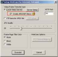
If you wish to send the captured images to another web server or to a different location, click on [FTP Transfer file] > [FTP Setup] and the Setup FTP dialog box will appear.
Connection retries If failed in FTP upload, repeat the online number (Max 999)
Retry delay Means the seconds to be waited for the online retry (Max 9999)
[JPG Quality]
Video quality may be adjusted by moving the slide bar. The higher the value, the better the quality. Better video quality needs more storage size.
[Frame Page Title Color]
This refers to the date/time captioned on the video. It can be displayed in transparent, black or white.
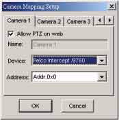
[Camera Mapping Setup]
You may set up PTZ Dome corresponding to each camera and control through Browser.
6. Click [OK] button to apply your setting and [Execute] button to enable Webcam server.
7.2 Start WebCam System
After you have properly setup GV-System's Webcam server it will be ready to send video stream over the Internet. There are four functions available for Webcam System, which are Mpeg4 Encoder Viewer, JPEG Image Viewer, Remote Play Back, and Server Information. This section will explain each function in detail.
7.2.1 Mpeg4 Encoder Viewer
The Mpeg4 Encoder Viewer is the most powerful remote monitoring option in the WebCam System. It basically run within the Internet Explorer and is capable of receiving live video stream from the GV-Systems over the Internet.
Start and Stop Mpeg4 Encoder Viewer
1. Run Internet Browser from your PC.
2. Key in GV-System's IP address in the browser's address box then press [Enter].
3. Select "Mpeg4 Encoder Viewer" and then click [Submit].
4. Select "MODEM" if you are using modem dial-up connection or "DSL/CABLE/T-1" if you are using a broadband TCP/IP connection.
5. In [Select Multi Window] area select the number of camera you wish to view in one web page then click [Submit]. Modem connection allows only one window because of the limited bandwidth. If you are using broadband Internet connection such as DSL or Cable Modem then select [DSL/CABLE/T-1] and you will be able to view up to 16
cameras at a time.
6. Click [Connect] button from the WebCam interface and the "Login" dialog box will appear. Input a valid user ID and password then click [OK]. If login successfully you will be able to view video over the Internet.
Function and Feature of Mpeg4 Encoder Viewer
Mpeg4 Encoder Viewer
 |
Click to connect to GV-System |
 |
Click to stop the connection |
 |
Click to enable speaker |
 |
Click to enable microphone |
 |
Click to login to a different GV-System |
 |
Click to select camera |
 |
Click to take a snapshot from the received video |
 |
Click to adjust the video quality in 3 levels |
 |
Click to save a video file |
 |
Click to switch to full screen mode |
 |
Click to bring out the I/O control panel |
 |
Click to bring out the PTZ control panel |
Change Server
The Change Server function allows you to change connection to a different GV-System.
Click on the [Change Server] button and the following dialog box will appear.
1. Click [New] button to create a new connection.
2. Enter a name for the new connection in the "Host" column.
3. Enter a valid user ID and passwords.
4. Enter the IP address of the GV-System you wish to connect to.
5. Specify port number in both Command Port and Data Port.
6. Click [OK] to establish connection to the server. This new connection will now be listed in the "Host" drop-down list.
7. To remove the connection simply selected from the "Host" drop-down list and click the [Delete] button.
Snapshot
Click on the [Snapshot] button and you will be able to capture an image from the video clip. Click [Print] button to print snapshot image to a printer or [Save] button to save the image as *bmp file.
File Save
Click on [File Save] button and you will be able to save video clip in *avi format.
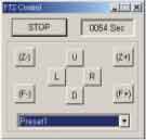
PTZ Control
Click on the [PTZ Control] button and the following PTZ panel will appear. PTZ cameras only allow one user to control at a time. Therefore, if there are several users trying to control the same PTZ camera in the same time, the camera will give priority to the first login user and to the next in the orders received. Each user will be given 60 seconds to control the camera. After the time expired, the system will switch the control to the next user in queue. The counter on the upper right corner serves two meanings, for user who is controlling the camera it indicates the remaining time of your control. For user who is waiting online it indicates the total waiting time.
 |
I/O Control
Click on the I/O control button to bring out the following I/O control panel. The I/O control
panel allows you to send signal to the output device over the Internet.
Click on [Start Control] button; use the drop-down list to select the module you wish to control.
Then click on one of the [Output] button to send signal to the device.
Two Way Audio
The MPEG4 Encoder Viewer provides two-way audio capabilities for the WebCam client. This feature delivers a full duplex audio communication with live video images between WebCam client and GV-System.
Setup GV-System's hardware for two-way audio
Before you can start using MPEG4 Encoder Viewer's two-way audio function you should first setup your GV-System so it is capable of running two-way audio.
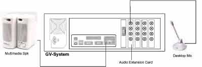
1. You must have a GeoVision audio extension card properly installed in your GV-System.
2. Connect a desktop microphone to the input of the audio extension card. Make sure you have AC power supply to your desktop microphone.
3. Connect a multimedia speaker to the audio input of your sound card.
 |
Setup audio device for two-way audio
In GV-System main screen, click on the [System Configure] button and select "Camera/Audio
Install" from the menu. In the following dialog box, select the audio input where your desktop
microphone is connected to in the drop down menu. Enable "Rec Audio" option, then speak
gently to the microphone and see if the wave-in oscillator vibrates. Keep speaking into the
microphone while monitoring the wave spectrum in the oscillator. Use the "Monitor
Sensitivity" and "Gain Control" slider bar to adjust the audio quality. To achieve best possible
audio quality, the wave spectrum should be extended as broadly as possible but not hitting or
exceeding the upper and lower edge of the wave-in oscillator.
Setup WebCam Server for two-way audio
In GV-System main screen, click [Network] button and enable "WebCam Server" from the
menu and the following dialog box will appear.
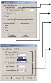 |
Step one: Select "Local Video Server" then click [Server Setup] button.
Step two: Click [Audio] tab in the "Server Setup" dialog box.
Step three: Enable "Server to Client" option. This enables your GV-System to transmit audio stream to WebCam client. In "Max. Channel" column, specifies the number of clients your GV-System is allow to send audio to. Select
the transmission audio codec in "Codec Selection".
Step four: Enable "Client to Server" option. This will allow your GV-System to receive audio stream from the WebCam client. In "Max. Channel" column, specifies the number of clients allowed to speak to your GV-System. In
"Codec Selection", choose the receiving audio codec.
Note: ADPCM requires 4KBps (4,000Bps) bandwidth while G.723.1 only requires 600Bps bandwidth. |
Setup WebCam client for two-way audio
1. Find a multimedia PC with Internet access and Microsoft Internet Explorer 6 web browser.
2. Make sure the desktop microphone and the multimedia speakers are properly connected to the sound card of your PC.
3. Log onto the Internet and key-in the IP address or domain name of the GV-System.
4. The MPEG4 Encoder Viewer will appear if logged on successfully. Input a valid user ID and passwords, and then click [OK] button.
5. Click on both the Microphone and the Speaker icons to enable the two-way audio feature.
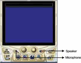 |
You should be able to perform two-way audio communication with a remote GV-System when all hardware and software are setup properly.
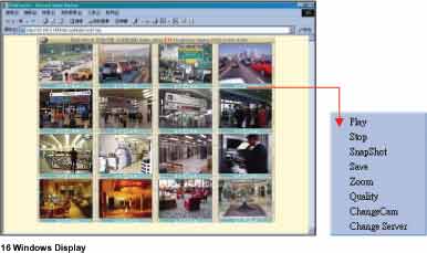
Multi Window Selection
If you are using a broad band Internet connection such as DSL or Cable Modem then you have the options to display 1, 2, 4, 8, or 16 camera windows under one web page. If the connected GV-System has 16 cameras then you can distribute them to each one of the Mpeg4 Encoder Viewer's camera windows. Or, you can have each window connecting to a different GV-System. This way you can connect up to 16 different GV-System under one web page.
Note:
Click on Option bar to bring up the user control menu.
7.2.2 JPEG Image Viewer
The JPEG image viewer is the second view option in WebCam system. It is capable of running on Mac OS browsers as well as Window browsers. Unlike the Mpeg4 Encoder Viewer, which receives live video streams, this one receives coninues Jpeg images from the GV-System. The JPEG Image Viewer is a ideal tool for users with low bandwidth and allow you to view only one camera at a time.
Start and Stop JPEG Image Viewer
1. Run Internet Browser from your PC.
2. Key in GV-System's IP address in the browser's address box then press [Enter].
3. Select "JPEG Image Viewer" and then click [Submit].
4. Input a valid user's ID and password then click [Submit]
5. If login successfully you will be able to view live video images using JPEG Image Viewer.
Function and Feature of JPEG Image Viewer
JPEG Viewer Control Buttons
 |
Select zoom-in, zoom-out, or fit into JPEG view window. |
 |
Click to scroll up, down, left, and right of the image. |
 |
Click to take a snap shot from the video. |
 |
Click to select view camera. |
7.2.3 Remote Play Back System for WebCam
The third option in the WebCam System is the Remote PlayBack viewer. Its functions are very similar to the Remote Playback System describe in Chapter 5. Which is allowing you to playback GV-System's recorded video from a remote area. One GV-System is capable of allowing 50 WebCam RPB client to login at the same time.
RPB Control Buttons
 |
Click to take a snap shot from the playback video. |
 |
Click to load recorded files from the GV-System. |
 |
Click to stop video
playback |
 |
Click to play video files. |
 |
Click to pause video playback. |
 |
Click to switch to full screen mode. |
 |
Click to download playback video to a specified folder. |
Search and Playback Recorded Files
The WebCam RPB system allows you to playback both video files and audio files. Audio file
are only available when your system is equipped with the optional audio recording function.
1. Click [Load] button to retrieve data from the GV-System.
2. Select the date in the folder tree.
3. All recorded video files within the selected date will be listed in the Event List window.
4. Use the camera select or audio select buttons to select input channels whose recorded files you want to locate.
5. Click and highlight the file you wish to view or listen to then press the [Play] button.
7.2.4 Server Information
The Server Info provides information and status of the login GV-System. These information will be refresh every 5 minutes giving you up to minute status information.
Server Information
| Last Update Time |
The last data refresh time. |
| Server Update Time |
Display the last server refresh time. |
| Recycle Log |
Display the time of last data deletion. |
| Camera On |
Display which cameras are activated. |
| Camera Off
|
Display which cameras are de-activated. |
| Camera Signal Lost |
Display which cameras are experiencing signal lost. |
WebCam Information
| WebCam Update Time |
Display the last login time. |
| WebCam Server
Startup Time |
Displays the startup time of the webcam server in the login
GV-System. |
| Mpeg4 Current
Channel(s) |
Displays the current online users whom are using Mpeg4 Encoder
Viewer. |
| RPB Curent
Channel(s) |
Displays current channel of RPB. |
| Audio Current
Channel(s) |
Displays current channel of audio. |
| WebCam Version |
Displays the version of your webcam software. |
Connect Info
| User IP Addresses
with login files |
Displays the IP address, login date, login time of WebCam users. |
Last 100 I/O Events
| Event XXX |
Displays the last 100 I/O activations. |
7.2.5 G-View Application
The G-View is a remote monitoring application for Pocket PC device. It can run on any PDA using Windows CE operating system. With G-View, you will be able to monitor your GV-Systems while on the move. This section will explain the setup and function of the G-View application in detail.
G-View Application Setup
The G-View application is included in your GV-System CD-ROM. This application should be installed in a PDA device with Windows CE OS.
1. Plug your PDA via USB or Com port to a PC installed with Microsoft ActiveSync.
2. Run Microsoft ActiveSync in the connected PC and make sure both the PDA and PC are synchronized.
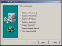
3. Insert GV-System CD into the CD-ROM drive of the PC and run Setup.exe in the CD-ROM root directory.
4. In the setup dialog box select "PDA Viewer for WinCE" and click [Next].
5. Click [Browse] if you wish to specify another destination directory otherwise click [Next] and follow the rest of the instruction to complete the installation.
Start and stop G-View application.
Once G-View is properly installed into your PDA device you will be able to use it to monitor your GV-Systems.
1. Click the [G-View] icon in your PDA to start G-View application.
2. Click the [Connect] button located at the lower left corner of the screen and the following screen will appear.
3. Input the IP address of the GV-System you wish to connect to in the "IP Address" column; enter a valid user's ID and password then click [OK].
4. If login successfully, you will be able to see the video coming to your PDA.
5. Click [Stop] button if you wish to terminate the connection.
Function and Features of G-View Application
The major function of G-View includes live video monitoring, PTZ camera control,
Camera zooming control, and snapshot.
G-View Application
 |
Click this button to take a snapshot from the video
clip |
 |
Use this drop-down list to switch cameras. |
 |
Use these buttons for focus-in and focus-out control |
 |
Use [+] and [-] button for zoom-in and zoom-out control. |
 |
Use these buttons to control left, up, down, and right of the PTZ camera. |
.
Server Info
Server Info
|
Server Update Time |
Display the last server refresh time. |
|
Recycle Log |
Display the time of last data
deletion. |
|
Camera On |
Display which cameras are activated. |
|
Camera Off |
Display which cameras are
de-activated. |
|
Camera Signal Lost |
Display which cameras are experiencing
signal lost. |
Web Info
|
WebCam Update Time |
Display the last login time. |
|
WebCam Startup Time |
Displays the startup time of GV-System's Web Server. |
|
Mpeg4 Current User |
Displays the number of online users
whom are using Mpeg4 Encoder Viewer. |
|
RPB Current Channel |
Displays the number of online users
whom are using RPB View. |
|
Audio Current Channel |
Displays the number of online users who are using Audio View. |
|
WebCam Version |
Displays the version of your webcam software. |
I/O Events
| |
Displays the time and date of the
invoke I/O device. |
7.2.6 Remote View Using i-mode
I-Mode is a mobile Internet service that was first introduced by NTT Docomo of Japan.Currently i-mode services are only available in Japan and Taiwan. But since i-mode is one of the most successful mobile Internet solutions and NTT is aggressively introducing I-mode solution to other countries, therefore, it is possible that it will be available in other countries in the future.
GV-System's i-mode concept
When using i-mode services, you do not pay for the time you are connected to a website or service, but are charged only according to the volume of data transmitted or received. Therefore, GV-System does not send live videos, instead, it will only send one images at a time and will not send another unless it is requested to do so. To request another image simply press the [Enter] key of your I-mode phone and you will be able to receive another
image from the system. The images are in GIF format with size of 96x72.
Enable GV-System's i-mode function
From your GV-System's main screen click [Network] > [WebCam Server] and enable "Support i-mode client". Your GV-System must be using a global IP address and should be accessible from the Internet.
 |
Connect to GV-System using i-mode
After enable the i-mode function you can now receive live images from the GV-System via an i-mode mobile phone. The interface and operation of your I-mode phone maybe different from the following example since the interfaces may vary from models to models.
1. Enter to the I-mode service page of your I-mode phone.
2. Select "Input web address" and enter the IP address of your GV-System in the Address column then press [OK].
3. Input an valid user's name and password then press [Submit]
4. Select the camera you wish to view then press [Enter].
5. If login successfully you I-mode phone will be able to receive live images from the GV-System
7.3 DMIP System
If your GV-System is using a dynamic IP address then it is nearly impossible for WebCam users to locate your GV-System once its IP address changes. DMIP is exclusive developed application for solving such problem. DMIP utilizes standard File Transfer Protocol (FTP) to upload files or data to a designated file server. This allows IP address of the GV System to be transferred to the file server periodically. You can now logon to the file server instead of GV System, file server will further redirect WebCam viewer to the GV-System.
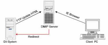 |
DMIP System Concept:
There are 3 major components required in the DMIP concept, which are DMIP-Server, GV-System, and client PC with web browser.
DMIP Server: Act as the FTP server and web server. This server must have a static IP address. You can setup your own DMIP Server or you can use the one already setup by us.
GV-System: The GV-System should be installed with DMIP application. The GV System does not require to having static IP address and should be connected to the network by
TCP/IP connection.
The client PC: Should have Internet access with either Microsoft Internet Explorer or Netscape Navigator installed.
DMIP Setup:
1. Install DMIP application in GV-System. Insert GV-System CD into the CD ROM drive of your GV-System and run Setup.exe in the CD root directory.
2. In the setup dialog box select "Register Dynamic IP" and click [Next] then follow the rest of the instruction to complete the installation.
 |
3. Run DMIP application in GV-System. Please go to [Start] > [Program] > [DMIP] > [Register Dynamic IP] and the DMIP setup window will appear.
A: Input the host name of your GV-System. (The host name will be used for identifying your GV-System in the DMIP server.)
B: Click "Use Default". This will set the upload IP address to a public DMIP Server. You'll notice that the FTP Login parameters are closed and you will not be able to make any changes or modifications.
C: Click OK and the status window should display the date, time, and the connection status.
4. If the connection between GV-Server and Geo-Server is establish successfully, you'll be able to
see a DMIP icon located in the lower left corner of the Window status bar.
Setup DMIP server
However, if you would like to build up your own DMIP server, please refer to the following
instructions to set it up:
1. Execute the IIS server 5.0 embedded in the Windows 2000 Server.
2. Build up a FTP server and allow the "Write" function.
3. Build up a Webserver and specify the path to the one which the FTP server specified. Remember, the access with "Write" is not allowed to be activated.
Note:
If necessary, you may also write a homepage for your own DMIP server.
|
 Surveillance