|
Main System Application
The Main System Application is
Windows-based GUI software that is used for control, setup, and
monitor the GV-System. There are two sections in this chapter: the first section will describe the function and
features of the main screen, while the second section describes the detail of main screen's function panel.
3.1 Main Screen Features
3.1.1 Status Panel
Status Panel Indicates the available HD space, system date/time, and the enabled network
functions such as Modem, TCP and MultiCast, etc...
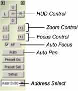
3.1.2 PTZ Control Panel
Before you can use the PTZ control panel you should have at least one PTZ camera installed
within your GV-System first. Click the PTZ control button on your GV-System main screen to
bring up the PTZ control panel. Your panel may look slightly different depending on the
camera model you're using.
| HUD Control: |
Controls the up, down, left, right action of your PTZ camera. |
| Zoom Control: |
Controls the zoom-in zoom-out action of your PTZ camera. |
| Focus Control: |
Controls the focus-in focus-out action of your PTZ camera. |
| Auto Pan: |
Directs camera to scan thru its entire range. |
| Preset Go: |
Directs camera to cycle thru its preset positions. |
| Preset Set: |
Allow you to set camera's preset positions. |
| Address: |
Specify the Com port address of your
camera. |
3.1.3 I/O Control Panel
Press the I/O icon to open the I/O control interface.
I/O Input Panel:
The I/O input panel displays the status of the input sensors from module 1 to
module 9.
I/O output panel:
Sending the output signals to the relays or alarms of module 1 to module 9. (PT811 support
output 1~8, GV-IO support output 1~16)
3.1.4 Camera Select Panel
Press the number of each desired camera to Zoom in or press the Num1~9, 0 and F1~F6 key
for shortcut, please refer to p. 30 for Fast Key Reference in this manual.
3.1.5 Display Layout Panel
The display layout panel allows you to choose from 8 different display layout options.
3.1.6 Exit and Minimize Button
The [Exit] button contains four functions: Login/Exchange User, Logout User, Minimize, and Exit.
| Login/Exchange User: |
Allows you to login as a different user. |
| Logout User: |
Allows you to logout from the system. |
| Minimize: |
Hide main screen in Windows status bar. |
| Exit: |
Allows you to shutdown the system. |
3.1.7 System Location Display
[Location Name]: Allow you to add or edit the name or location of your GV system.
[Recycle]: This icon appears when the system is in the process of recycling.
3.1.8 Camera View Window
The camera view window displays the video event from your video cameras.
Snapshot:
[Snapshot] allows you to capture a camera image and save them as avi., bmp., Jpeg., or tif.
files. Click on the camera caption of the camera view window, and the following dialogue box
will appear. You may tag camera descriptions in the image file such as time/date, camera
number, location, and choose color for the description
background by clicking the option boxes below.
Use [Ctrl+ Num 1 ~ 9 0 and F1 ~ F6] on your keyboard for shortcut.
[Time/Date] Click to tag time and date in the snap shot image file.
[Camera] Click to tag camera numbers in the snap shot image file.
[Location] Click on this box to tag camera location in the snap shot image file.
[Transparent] Click on this box to make the description background transparent.
[Color box] Click to select text color for the tag description.
3.2 Function Panel
The Function Panel provides access to most of the GV-System's function and configuration. There are
six buttons in the function panel with each button containing its own menu.
3.2.1 Start/Stop Monitoring
You may consider  [Start/Stop Monitoring] button as the recording button of the system.
Click on this button and the following menu will appear that allows you to select between start
recording on all cameras or by individual camera.
[Start/Stop Monitoring] button as the recording button of the system.
Click on this button and the following menu will appear that allows you to select between start
recording on all cameras or by individual camera.
To start recording on all cameras simply select "Start All Monitoring" option. When in
recording, the camera caption will be displayed in red color. To stop recording, select "Stop
All Monitoring" and all recording will be stopped (You may use the [F7] key on your
keyboard as Start/Stop Monitoring shortcut key).
You can also choose the camera you wish to record by clicking on the camera name within
the menu. A check sign will appear before each camera name indicating its in recording
mode. You may uncheck them to stop the recording.
3.2.2 Schedule
Click on the
 [Schedule] button and the following dialog box will appear. There are two
types of surveillance schedules in GV-System: the video surveillance schedule and the I/O
surveillance schedule. Each can be setup in weekly basis or exclusively by date. Your
GV-System is capable of running multiple surveillance schedules; therefore, you can assign
each camera with a different schedule. All surveillance schedules will be displayed in the
schedule list window.
[Schedule] button and the following dialog box will appear. There are two
types of surveillance schedules in GV-System: the video surveillance schedule and the I/O
surveillance schedule. Each can be setup in weekly basis or exclusively by date. Your
GV-System is capable of running multiple surveillance schedules; therefore, you can assign
each camera with a different schedule. All surveillance schedules will be displayed in the
schedule list window.
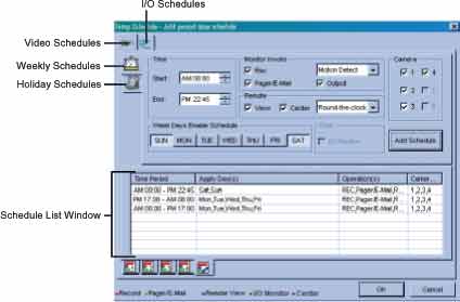 |
How to setup video surveillance schedules:
Before you can start a surveillance schedule you should have at least one schedule setup
first. Setting up a surveillance schedule is like assigning a task to your GV-System. You
specify the rules and timetable for the cameras and the cameras will perform these tasks
base on your specification.
First, start by creating a weekly camera surveillance schedules. Click [Video schedule] tab
and select [Weekly Schedule] and follow the steps below to complete the setup.
Step one: Select time period
Set starting and ending time of your preferred schedule event.
 |
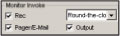
Step Two: Specify monitor invoke options
Rec: Click on the Rec option to enable or disable recording function.
Recording Mode: Use the drop-down menu to choose between Round-the-clock
recording mode or Motion-detect recording mode. Round-the clock mode applies full
time recording during the schedule period while Motion-detect mode records only when
motions are detected.
Pager/E-mail: Click on the Pager/E-mail option to enable or disable Hotline Alertsduring the surveillance schedule. The Hotline Notice will send alerts to users by pager
or email when motion detector or I/O sensor are trigger.
Output: Click on the Output option to enable or disable sending output signals to the
output pin during the surveillance schedule. This option requires the optional GV-IO
hardware.
 |
Step Three: Set remote function
View: Click on the view option to enable or disable remote view function during the
surveillance schedule.
Center: Click on the center option to enable or disable sending pictures to
GeoCenter.
Step Four: Camera select
Select cameras you wish to be used during the surveillance schedule.
Step Five: Day Select
Select the days you with to be included in the weekly schedule. For example, if you
wish to apply this schedule from Monday to Friday, simply select them by push down
each day's button.
Step Six: Add schedule to the list
You have now complete the setup of this weekly schedule, click
 [add schedule]
button to add this schedule to the list. Detail of your schedules will be listed in the
Schedule List Window. [add schedule]
button to add this schedule to the list. Detail of your schedules will be listed in the
Schedule List Window.
You can also view each camera's surveillance schedule in bar chart view by clicking the
camera select tab below the Schedule List Window. The bar chart are displayed in 5
different colors with each color representing a specific function.
| [Red]: |
Recording Function |
| [Green]: |
Pager/Email Notification |
| [Blue]: |
Remote View Function |
| [Jade]: |
I/O Monitor Function |
| [Purple]: |
Center Function |
Note:
You can add as many schedules as you wish to the schedule list. For example, if you
wish to have a different surveillance schedule for Saturday and Sunday, simply define
another surveillance schedules as describe in the above steps, select SUN and SAT
button and click [Add Schedule] button to add it to the schedule list. Your weekend
schedule will appear next to the weekday schedules in the Schedule List Window.
If you wish to change a schedule, simply highlight it from the list, change the settings as
you wish then click
 [Modify Schedule] button to apply your changes. If you wish
to remove a schedule from the list, highlight it from the list and press the [Delete] key of
your keyboard to remove it. [Modify Schedule] button to apply your changes. If you wish
to remove a schedule from the list, highlight it from the list and press the [Delete] key of
your keyboard to remove it.
Setup video surveillance schedules for Holidays:
You may want to setup different schedules for Holidays such as Christmas or New Year.
You can setup all holiday under the same schedules or you can assign different schedules for
each holiday. Click the [Holiday schedule] control tab to switch to holiday setup window.
The only difference between the Weekly Schedule and Holiday Schedule is the day selection
area, the rest of the setup are same as the weekly schedule setup.
Please follow the Weekly Schedule's setup procedures from Step One to
Step Four, and then follow the rest of the steps to complete the Holidays Schedule setup.
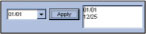
Step Five: Day Select
Click on the drop-down menu and select the date from the pop-up calendar. Click the
[Apply] button to add your selection to the right hand side column. Specify the rest of
the parameters as in the weekly schedule setup.
 |
Step Six: Add Schedule to the list
Click
 [Add Schedule] button to add this schedule to the list. You'll notice that
this holiday schedule now appears next to your weekly schedule. [Add Schedule] button to add this schedule to the list. You'll notice that
this holiday schedule now appears next to your weekly schedule.
How to setup I/O surveillance schedules:
The I/O surveillance schedule works similarly as the video surveillance schedule with simpler
operation. Click on the I/O schedules control tab to switch to I/O schedule setup window.
Step one: Select time period
Set starting and ending time of your preferred schedule event.
Step Two: Select I/O Device
Select the I/O device to be included in this surveillance schedule.
Step Three: Select Date
Select the days you with to be included in this schedule. For example, if you wish to
apply this schedule from Monday to Friday, simply select the days by clicking its button.
Step Four: Enable I/O Monitor
Click on I/O monitor to enable or disable I/O monitoring during the surveillance.
Step Five: Add Schedule to the list
Click
 [add schedule] button to add this schedule to the list. [add schedule] button to add this schedule to the list.
3.2.3 System Setup and Configuration
Press the
 [System Configure] button or [F9] shortcut key on your keyboard for system
configuration setup. There are total 8 options included in the Configure menu. This section
will explain each option in detail. [System Configure] button or [F9] shortcut key on your keyboard for system
configuration setup. There are total 8 options included in the Configure menu. This section
will explain each option in detail.
System Configuration
The System Configuration window includes four types of configuration setup: General
Setting, Camera Setting, I/O Device Setting, and Hotline/Network Setting. You can select
between these settings by clicking on its control tab.
General Setting
[Startup]
Select the check box to automatically start selected features at GV-system startup.
Start Monitor: Select the check box to automatically Start All Monitoring at GV-system
startup. Three monitoring modes are available:
| Monitor All: |
All cameras automatically start recording at GV-system startup. |
| Schedule Monitor: |
Start recording based on preset schedule. |
| I/O Monitor: |
Start recording based on I/O device setup. |
Network Server: Choose which network function you wish to enable after system startup.
The network function includes: Multicast Server, TCP/IP Server, Webcam Server, Modem
Server and Connect to Center.
Directdraw Overlay: If this option is enable then your system will be able to switch to full
screen mode. However, your VGA card will need to support direct draw overlay to use this
function.
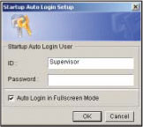
Startup Auto Login: Click to enable auto login function. Click on the arrow icon and the
following dialog will appear. Enter the ID and passwords of the account you wish to use for
auto logon. You can also specify whether to login in full screen mode or in normal mode.
 |
Panel Resolution: Select 800x600 or 1024x768 to fit your screen.
[Location Name]
Allow you to specify a name for your GV-system, maximum 14 characters.
[Log Storage]
Recycle: Select Recycle check box if wish to automatically delete files at disk space
shortage. If the Recycle option is not selected, the system will stop recording at disk space
shortage.
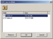
Click [Set Location] to create folders for recorded files. This dialog box lists path of the
recorded files, and disk capacity available for storage in MB. Click on the folder icon to
create another location.
 |
When the available storage space is lower than 500MB, recorded files will automatically be
saved to next available folder.
Note:
For GV-100, 150, and 250, the minimum hard disk required for recording is 500MB. For
GV-600, 650, 750, and 800 the requirement is 800MB.
[Caption]
Allow you to add camera captions on the upper left corner of the camera view window. You
have a choice to add either camera ID only or camera ID and camera name.
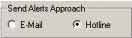
[Send Alerts Approach]
Choose E-mail to send alerts to pre-set E-mail account; choose Hotline to send alerts to
pre-set pager or telephone number.
 |
[Exit Option]
Two options are available: Auto Shutdown Windows and Auto Restart Windows. If you select
auto shutdown windows the system will automatically shutdown Windows OS after you exit
GV-System. If you choose auto restart windows then it will automatically restart Windows OS
after you exit GV-system.
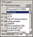
[PTZ Control]
The PTZ Control allows you to setup installed PTZ cameras. Select the make and models in
the drop down list menu and click the PTZ setup button to activate it. If you cannot find your
PTZ camera within the drop down list then most likely its not supported by the GV-System.
 |
[Monitor Option]
Specify how many seconds to delay monitoring function after system startup.
Start Delay: Enable this function and the system wil delay the recording for a preset
time after an alarm.
Post-Rec Motion: Enable this function and the system can be recorded for a preset
time after motion detection occurs. (1 ~ 10 seconds)
Video Lost/IO Error Alerts: Enable this function and the system will send Email or
Hotline alerts to notify you if your camera or I/O device lost signals.
Pre-Rec Motion: Allow you to record pre-motion images for a pre-set time prior to
motion. To use this feature, follow these steps:
1. Select the [Pre-Rec Motion] check box to enable this feature.
2. Click the blue [Arrow] button next to [Pre-Rec Motion] to bring up the [Pre-Record
Setup] dialog box.
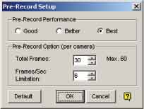 |
Pre-Record Setup
Pre-Record Performance: There are 3 preset pre-recording performance settings:
Good, Better and Best. The amount of physical memory of the computer, which the
GV system is running on, will determine the pre-recording performance--the duration
time of the pre-recording.
Table below shows the maximum pre-recording frame rate of each preset, and the
physical memory requirements:
| |
Good |
Better |
Best |
| Maximum pre-recording
frames per camera (fps) |
15 fps |
30 fps |
60 fps |
| RAM required |
128 MB |
256 MB |
512 MB |
| The recording frame rate is calculated based on a 320x240 recording size. |
Pre-Record Option (per camera)
[Total Frames] It allows you to set the maximum pre-recording frames of a camera.
[Frame/Sec Limitation] It allows you to set the maximum pre-recording frame rate
(fps) of a camera.
Dividing the [Total Frames] by [Frames/Sec Limitation], you will get the pre-recording
duration of each camera (in the above case, each camera will start to record 5 seconds
prior to motion).
Note:
Frame/Sec Limitation cannot exceed the preset recording rate of the GV system being
used.
[Event Log Size]
It allows you to select the length of each event log from 1 to 5 minutes. If you select "5 Min,"
then a 30-minute video clip will be break into six 5-minute files.
[Camera Scan]
It allows you to specify the Scan Delay from 1 to 10 seconds. Click on the [Arrow] icon and
you can choose between single camera scan or four cameras scan.
[Video Record]
Check the box to enable Digital Watermark Protection to prevent alteration or distortion of
recorded data. The purpose of digital watermark is to provide copyright protection for an
image or video clip. Watermark is not visible to human eyes, but the embedded watermark
software of GV-system can help identify the authenticity of the recorded images.
Camera Setting
Camera setting window allows you to configure each camera's motion detection sensitivity,
recording quality, video adjustment, and etc... Each camera has its own setup window and
you can use the camera control tab to switch between the cameras.
[Camera Name]
You can specify a name for each camera. You can name each camera according to its
location or usage. For example, you can name camera 1= Lobby, camera 2= Elevator 1, and
etc...
[Rec Control]
The Rec Control area allows you to set each camera's recording quality. The camera's
recording quality is based on its resolution and compression rate. Higher quality picture will
require more storage spaces.
Recording Quality: Allows you to adjust the video quality in 5 levels. Higher value equals to
lower compression rate.
Resolution Button: Click on the arrow icon next to the Recording Quality slide bar to switch
between the available resolutions.
Frame/Sec: Allow you to adjust camera's recording frame rate. There are three options
available: Smart, High, and Low.
[Smart]: When Smart Recording Option is selected, the system will distribute as
many frame rates as possible to the camera where motion occurs.
[High]: System will distribute high percentage of frames (not a definite frame
number) to the selected camera while the other cameras will share rest of
the frame rates. Assuming that all cameras are in action, selecting [High]
ensures this camera always receive higher frame rate than the rest of the
cameras. Effect can be seen in both preview mode and record mode.
[Low]: System will distribute low percentage of frame rates to the selected camera.
Assuming that all cameras are in action, certain cameras are of least
importance. System can be set [Low] in order to allow frame rate to go to
more important cameras.
Frame Rate Setup: Allows you to limit camera's maximum recording frame rates. If the value
you specify is 10 then it means this camera will not exceeds 10 frames/second. However it
does not guaranteed that it would always record in 10 frames/second, as the actual recording
frame rate will be dependent on the performance of your system. This setting will take effect
in all recording mode including Smart, High and Low.
 |
[Motion Detect]
This area allows you to adjust the build-in motion detector's sensitivity level from 1 to 10. The
higher the value, the more sensitive the system is to the motion. Movement will be recorded
when the motion exceeds the value. By applying mask to the camera window, system will
ignore movements under "Mask" area. For example, you wish to observe your office but not
the moving traffic outside the street. You may mask the office window containing traffic
movements so that system will ignore the traffic, and record only the areas of the office that
are not masked. Icons used to modify the mask area are as followed:
[Monitor Control]
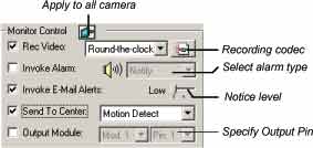 |
Rec Video: Click this option to enable or disable this camera's recording function. The
drop-down-menu allows you to choose between [Motion Detect] or [Around the Clock]
recording mode. Click on the recording codec button to select between Wavelet and Mpeg 4
recording format.
Invoke Alarm: By enable this camera's Invoke Alarm option the system will be able to
generate a alarm sound when the camera detects a motion. There are 7 types of alarm sound
to choose from in the Alarm type drop-down menu.
Invoke E-Mail Alerts: Enable this function and the system will send E-mail alerts when
motions are detected. You may use the slider bar to select notice interval, whereas [High] =
0.5 second, [Medium] = 1 sec., and [Low] = 1.5 sec.
Send to Center: If you have installed Center at a remote site or you have applied the
service to Center, You may define how to send the live video to Center, by either [Motion
Detect] or [Round-the-Clock] functions.
Output Module: Set the output of the camera to the module when invoked. The maximum
controlled output is 9 modules, with 8 pins for PT811Device and 16 pins for GV-IO Device.
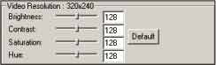
[Video Resolution]
Allow you to adjust camera's video characteristic such as brightness, contrast, saturation,
and hue.
 |
I/O Device Setting
External devices can be connected to the GV-Systems via I/O modules (GV-NET, GV-IO,
GV-RELAY). This section will explain on how to configure and integrate I/O devices in the
GV-System.
[Select I/O Device]
Before using the I/O modules, you have to setup the GV-System to recognize them first. You
should have at least one GV-NET module connected to the Com port of your computer. Now
in the [Select I/O Device] area choose the module you wish to install in the [Device] drop
down menu, select Com port and address, then click [Format Add] button. The [Add] button
will be unlocked if the system successfully found your module. Click the [Add] button and this
module will appear in the Module List Window.
Note:
When you add several I/O devices (Max 9) in one GV-Net, you cannot do Format Addr.
at the same time. First you must Format Addr. to I.O devices one by one, than add all
I.O device in GV-Net.
[Input Setup]
If you have PT811 module connected and is properly setup within your system, then you will
be able to configure its functions in the input configure area. Each PT811 can connect up to 8
input devices. You may use the [Input Select Button] to choose the device you wish to
configure.
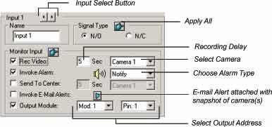 |
Name: You can specify a name for each input device in the Name text column.
Signal Type: Select signal type for your input device. You may use the [Apply All]
button to apply your selection to all input devices.
Rec Video: Check this option if you wish to use this device to trigger recording
(sensors or detectors). You may select which camera to record in the
Camera Select drop down menu and specify the recording delay.
Invoke Alarm: Check this option if you wish to send alarm to the GV-System when this
input device is trigger. You may select the alarm type in the drop down
menu.
Send to Center: Check this option if you wish to send an image to the Center when this
device is trigger. Select the camera in the drop-down menu.
Invoke Notice: Check this option to have GV-System notify you by Telephone/Pager or
Email when this device is triggered. Click on the arrow icon to choose
camera(s) snapshot that pictures you want to send by email when this
device is triggered.
Output Module: If the input device is invoked, the system will send a signal
automatically to an output pin.
[Output Setup]
Use the Output Select Arrow Buttons to select the output for modification. GV-IO supports
up to 16 outputs, and PT811 supports up to 8 outputs.
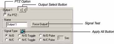 |
PTZ: Connect to the panel
Name: Name your device.
Force Output: Click on the [Force Output] button to send signal to the output device.
Signal Type: There are six signal types available: N/O (Normal Open), N/O Toggle,
N/O Pulse, N/C (Normal Close), N/C Toggle, and N/C Pulse. Choose the one of suit mostly to the device that you're using.
The N/O Toggle or N/C Toggle signal type is output high mode until press again to
output low. You may also specify the pulse duration for pulse type signals.
Notes:
The same port cannot connect to both PTZ Dome and I/O device at the same time.
HotLine/Network Configuration
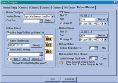 |
[Modem Configure]
If you have installed modem in this PC, select the corresponding device and port, then press [Detect] button to test your modem.
Note: We do not recommend using internal modem (PCI or ISA).
[HotLine Notice]
You may specify 3 different telephone/pager numbers for HotLine Notice. You can attach text
messages if you wish to send alerts by pager or audio messages if you wish to send alerts by
telephone.
How to Setup Hotline Notice Function
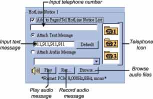 |
1. Click on the telephone icons.

2. Enable [Add to Pager/Tel hotline Notice List] option by clicking the check box before it.
3. Enter the telephone number or pager number you wish the system to dial to in the
telephone number column.
4. If the number you have entered is a pager number then you can enable [Attach Text
Message] and input text messages in the text column. Therefore, when the system
notifies you by pager, your pager's screen will appear with these text messages.
5. You can also attach audio files if you want the system to notify you by telephone. If you
already have a pre-recorded message you can click [Browse] button to locate the
message then click [Play] button to listen to it. If you wish to record your own message,
click [Rec] button and follow the procedures below to create your own message. To
record messages, you must have a microphone connected to the MIC input of your
GV-System's sound card.
Step 1: Press the recording button to start recording. Speak the message script
clearly to the microphone and press stop button when you're finish.
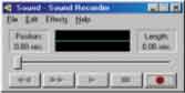 |
Step 2: You can press the play button to review the recording. If you're sure this is
the recording you want then choose [File] > [Save as] > [Change] and in the
following dialog box select PCM 8,000 Hz, 8-bit Mono (the only format
supported) and click OK.
Step 3: Try to playback this message in [HotLine Alerts] dialog box. Click browse to
locate the file you've just recorded and click the [Play] button to play this
recording. If a format other than PCM 8,000Hz, 8-bit mono is selected then
an error message will pop up and you will not be able to play that recording.
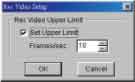
[TCP Server]
Allow you to setup GV-System's TCP server. Enable [Assign IP] option to enable the drop
down list at the right hand side. Select the network card within the drop down list and your IP
address will be displayed in Bind IP. The default port number for TCP server is 3550; you may
assign different port by entering the port number in the [Port:] text column.
[Multicast Server]
Allow you to setup the Multicast server; its operation is similar to the TCP server setup
describes above. The default port number for Multicast server is 3650.
Note
If you are using Dynamic IP, GV-Series system will automatically detect the IP Address
per minute and replace IP so as to ensure re-engagement of remote end
RemoteView IP Multicast WebCam and RemotePlayback system.
[HotLine Option]
The HotLine Notice Interval allows you to specify the time interval between each notification.
For example, if the interval time you specified is 5 minutes, then the system will call to your
phone/pager every 5 minutes if motion still persist. The system will stop calling when no
motions are detected.
[HotLine Attach Audio Message]
You can specify how many times to repeat the audio message when the system notifies you
by Telephone.
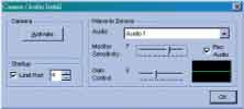
Camera / Audio Install
Click
 [System Configure] button and select "Camera / Audio Install" option and the
following window will appear. [System Configure] button and select "Camera / Audio Install" option and the
following window will appear.
 |
[Camera]
Activate: Click on the [Activate] button and a camera list menu will appear. You'll find a
check box before each camera; click on the check box to activate or
deactivate the cameras.
B/W: When the picture is jammed due to installation of both color and
monochrome cameras on the system, select B/W to change all video display
to monochrome. (Available only on GV-200)
[Start Up]
You may set the channel number for the camera to be activated and start up the function in
next program execution.
Note
If you are using 16Cam / 4Port then Start Up, Camera Scan will disclose the desired
Camera number by the quantity of Port so as to scan camera function.
[Wave-in Device]
Allow you to setup GV-System's audio function. Each channel can be configured separately.
Choose the audio channel in the drop down list and adjust the parameters accordingly to your
specification. The Rec Audio option should be enabled if you wish to activate audio recording
function. The recording is control by the Monitor Sensitivity bar, which is adjustable from level
one to level 10; the higher the value the more sensitive it is to environmental sound and is
more likely to trigger the recording. The Gain Control bar allows you to add boost to the audio
input level.
 |
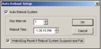
Auto Reboot Setup
Click  [Configure] button, select "Auto Reboot Setup" from the menu, and the following
dialog box will appear. Click on Auto Reboot System to enable this function and the settings
in the dialog box will be unlocked. In [Day Period] you may specify the day interval of each
auto-reboot (range from 1 ~14 days), and in [Reboot Time] specify in what time you want the
system to perform auto reboot.
[Configure] button, select "Auto Reboot Setup" from the menu, and the following
dialog box will appear. Click on Auto Reboot System to enable this function and the settings
in the dialog box will be unlocked. In [Day Period] you may specify the day interval of each
auto-reboot (range from 1 ~14 days), and in [Reboot Time] specify in what time you want the
system to perform auto reboot.
The [WatchDog Reset if Reboot System Suspend and Fail] option is for avoiding system
lockup during an auto reboot. Enable this function allows the Watchdog function in your
GV-Series video capture card (available in GV-600, GV-650, GV-750, and GV-800 only) to
reset your system if auto reboot fail to restart for more than 5 minutes.
Note:
The WatchDog option will be closed if the option of "Auto run GV-System when window
startup" is not enable during the main application installation.
Password Setup
Click
 [Configure] button, select "Password Setup" from the menu, and the following
dialog box will appear. The Password Setup function allows you to define a user profile for
each GV-System user. A user's profile determines which functions a user is allow to access.
Only the supervisor level users can access to Password Setup function. [Configure] button, select "Password Setup" from the menu, and the following
dialog box will appear. The Password Setup function allows you to define a user profile for
each GV-System user. A user's profile determines which functions a user is allow to access.
Only the supervisor level users can access to Password Setup function.
Add New User
Step 1: Click the [New] button located below the User list window and the New
Account dialog box will appear.
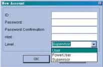 |
Step 2: Input the ID name and the passwords for your new user, you are required to
input passwords one more time for confirmation.
Step 3: You may add a probable hint for your user in case they forgot their
passwords (this function is optional). For example, you may use this user's
birthday as the password hint. Therefore, by entering their birthday in the
Hint column will allow the system to display their passwords.
Step 4: Use the drop down menu and select an authorization level for your user.
Four levels are available: Supervisor, PowerUser, User and Guest.
Supervisor will have access to all GV-System functions while PowerUser
and User will be restricted to use some of the functions. (You can specify
which functions to grant or deny for the PowerUser and User later in Edit
User Profile.) Guest level user is allowed to view video only and is restrict
from all GV-System functions. You cannot create additional Guest profile
as they share one universal ID and passwords.
Step 5: Click [OK] and the new user will be added. User information will appear in
the User Profile area and the accessible functions will appear in the function
area.
Edit User Profile
Step 1: Locate the user you wish to edit in the User List window. You may use the
[Find] button to find the user profile more quickly.
Step 2: In the User Profile area you can change user ID and passwords.
Account is disabled: Enable this option if you wish to disable this account
but would like to keep the profile in the user list.
Login this ID automatically: Enable this option if you wish to use this
account for auto login.
Step 3: You can grant and deny users authorization to access GV-System's function
in the Functions area. Functions are categorized in 7 categories; use the tab
control button to select between them. Each category will have a list of
function with a check box before them. Check the box to grant function and
uncheck to deny it. Click on the name of function and a yellow tag will appear
with a brief description of the function.
Step 4: When finish, click [OK] button to save your changes to the user profile.
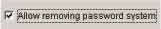
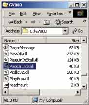
Allow removing password system
This option allows supervisors to execute passUnInstall.exe and remove the passwords in
case of the passwords are lost.
 |
 |
E-mail Setup
Before you can use Invoke Notice Email function you'll need to setup GV-system's email
account first. Click
 [Configure] button at GV-System main screen's function panel,
select Email Setup, and the following dialog box will appear. [Configure] button at GV-System main screen's function panel,
select Email Setup, and the following dialog box will appear.
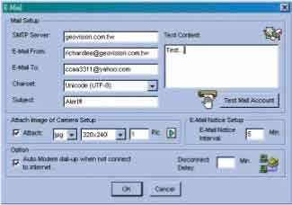 |
[Mail Setup]:
Step 1: Input your mail server name in "SMTP Server" column.
Step 2: Input a reply email address in "E-Mail From" column (optional).
Step 3: Input the email address you want to send alerts to in "E-mail To" column.
Step 4: Select a charset most suitably to your specification from the drop down menu.
Step 5: Enter subjects and text content in the text column next to them. Both are
optional function and you can leave them empty if you do not require them.
Step 6: Click [Test Mail Account] button to see if the Email function were setup
properly.
[Attach Image of Camera Setup]:
You have the option to attach an image of the captured event when the system notifies you by
email.
Step 1: Click [Attach] check box to unlock this function.
Step 2: Use the drop down menu to choose between png or jpg image format.
Step 3: Select image size, there are 3 sizes available: 320 x 240, 160 x 120, and 120
x 90.
Step 4: Specify how many pictures you like to send out (accept 1~6 pictures).
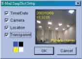
Step 5: Click on the arrow icon and the snapshot setup dialog box will appear. You
can tag Time/Date, camera name, and location name on the image file by
checking the check box before them. Use the color box to choose the text
color most suitable to the camera's surrounding environment. Check
[Transparent] if you wish to make the text background transparent otherwise
the text background will appear in black.
 |
[Email-Alerts Setup]:
If the camera continues to detect motions then the system will continuously send emails to
notify you. You can specify the time interval between each email. The default time interval is 5
minutes (configurable from 0 to 60 minutes); therefore if motions occur for more than 15
minutes then you will receive 3 emails. If motions occur for less than 5 minutes, then you will
receive only one email.
[Option]:
If you are using a dial-up modem then it is unlikely that your system will stay online
continuously. Therefore, you can use the [Auto Modem dial-up] option and the system will
automatically dial-up to the Internet when it is instruct to send email notification. The
Disconnect Delay option allows you to specify how long you want the system to stay online.
The default is 5 minutes (configurable from 0 to 30 minutes), which also give you some time if
you want to connect to the system by Webcam viewer or other Geovision remote view
applications to view the incident. The system will disconnect itself after 5 minutes or specified
time.
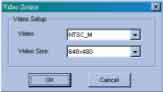
Video Source Setup
Your GV-System supports both NTSC and PAL video standards. Click
 [Configure] button,
select [Video Source], and use the [Video Standard] drop down menu in the dialog box to
select the correct standard for your camera. [Configure] button,
select [Video Source], and use the [Video Standard] drop down menu in the dialog box to
select the correct standard for your camera.
 |
Performance
Click
 [Configure] button then select "Performance" and the following menu will appear.
This function is only available to GV-650, GV-700, GV-750 and GV-800. [Configure] button then select "Performance" and the following menu will appear.
This function is only available to GV-650, GV-700, GV-750 and GV-800.
Preview Master: The Display speed increases because the system resource will focus on
the monitoring after clicking Preview Master icon.
Both Master: Both display and recording speed is at the average because the system
resource is allocated equally.
Record Master: The recording speed increases because the system resource will focus on
the recording after clicking on Record Master icon.
 |
Video Attribute Setup
The Video Attribute Setup allows you to separately adjust each camera's video characteristic.
There are four parameters available: Brightness, Contrast, Saturation, and Hue. Use the slider
bar next to each parameter and adjust them to your preference. You may use the default
button to reset all four parameters. Use the Camera Select button to select between cameras
or you may also use the Apply All button to apply your setting to all cameras.
Full Screen
Click
 [Configure] button, select [Full Screen] from the menu, and the system will switch to
full screen display. Point your mouse to the camera view window, right click on the mouse and
select [Full Screen Mode Switch] to switch back to normal screen display. [Configure] button, select [Full Screen] from the menu, and the system will switch to
full screen display. Point your mouse to the camera view window, right click on the mouse and
select [Full Screen Mode Switch] to switch back to normal screen display.
3.2.4 View Log
On the function panel click
 [View Log] button and this will launch the view log application.
The view log application allows you to playback recorded video files or image files. View Log's
detail description will be explained later in Chapter 5. [View Log] button and this will launch the view log application.
The view log application allows you to playback recorded video files or image files. View Log's
detail description will be explained later in Chapter 5.
3.2.5 Camera Scan
Click the  [Camera Scan] button or the [F11] key of your keyboard to star/stop camera
scan function. [Camera Scan] button or the [F11] key of your keyboard to star/stop camera
scan function.
3.2.6 Network Functions
Your GV-System can be connected to various remote view applications (each remote view
application will be explained in detail in the later chapters). However, before you can use
these remote applications, its related application or network server should be enabled first in
the GV-system.
3.3 Fast Key References
|
Esc |
Return to default screen |
|
Num 1~ 9, 0 and F1~ F6 |
Zoom in camera window |
|
F7 |
Start Monitor /Stop Monitor |
|
F8 |
Start Schedule Monitor/Stop Schedule Monitor |
|
F9 |
Set up System Configuration |
|
F10 |
Start Viewlog (playback) |
|
F11 |
Start/Stop camera scan |
|
F12 |
Network functions |
|
M, m |
Start/Stop Modem connection |
|
T, t |
Start/Stop TCP/IP connection |
|
W, w |
Start/Stop Webcam connection |
|
I, i |
Start/Stop IP Multicast connection |
|
C, c |
Start/Stop Center connection |
|
F, f |
Start/Stop Full Screen |
|
L, l |
Login / Exchange User |
|
O, o |
Logout User |
|
Z, z |
Minimize |
|
X, x |
Exit |
|
Page Up |
Zoom in previous camera |
|
Page Down |
Zoom in next camera |
|
Ctrl+ Num 1 ~ 9, 0 and F1 ~ F6 |
Snapshot |
|
, |
Change size of camera windows |
|
 Surveillance