|
Hardware Installation
The hardware components included in your system may vary depending on the model or optional features you purchased. This chapter will describe all available hardware components of the GV-System and its installation procedures.
1.1 Video Capture Device Installation
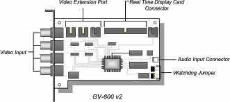
1.1.1 Install GV-600 Hardware
The GV-600 uses a PCI interfaced card and is one of the models that support
Real Time Display card and Audio Recording card. The GV-600 will support from 4 to 16 ports.
1. Power-off the PC.
2. Insert PCI card into PCI slots.
3. Turn on PC power. Windows will automatically detect the existing cards.
4. Now select the driver path in the CD directory
\Driver\GV600, 650, 700, 750, 800 to install the driver.
1.1.2 Install GV-650 / GV-750 / GV-800 Hardware
The GV-650, and the above are identical in card layout; the only difference is in the
performance. All models support the optional Real Time Display card and audio
recording card. The standard model starts from 4 ports with optional expansion to 8, 12, and 16 ports.
1. Power-off the PC.
2. Insert PCI card into PCI slots.
3. Turn on PC power. Windows will automatically detect the existing cards.
4. Now select the driver path in the CD directory \Driver\GV600, 650, 700, 750, 800 to install the driver.
1.2 Watchdog Installation for GV-Series Video Capture Cards
The Watchdog function is used to detect whether the surveillance system is alive or not.
In other words, if, for some reasons, a system is down or "hang up", the watchdog will restart and reset the system automatically if
the "live signal" is not received by the system for more than 5 minutes.
There are two units of reset button pin located in the lower right corner
of the GV-Series video capture card. One is connected to the reset jumper of the system motherboard, and the other is to the PC's
reset switch (please see illustration diagram below). Your system motherboards' RST pin position might be
different from the diagram below, please refer to your motherboard user's manual for the actual position.
1.3 Video Extension Card Installation
The GV-System comes standard in 4 video input channels with option to expand to 8, 12, or 16
channels. If you are installing an 8, 12, or 16 channels system then you will need to add video
extension cards to the video capture card. Each capture card can be connected up to 3 video
extension cards and each extension card will provide an additional 4 channels. The video
extension card's output cord should be connected to the captured card's video extension port
located in the upper left corner area as illustrated below. For model GV650, GV750, and GV800
users, the video extension ports are located in the right hand side area of your capture card.
1.4 Real Time Display Card Installation
The Real Time Display card is capable of feeding 480 fps to 16 video channels with each channel
running at 30 fps. Video can also be displayed to a TV monitor by using the TV-out connector. The
card is designed to work conjunctionally with your GV series video capture card; therefore, a direct
connection between both cards is required. The current model that supports Real Time Display
cards are GV600, GV650, GV750, and GV800.
1. Insert the Real Time Display card into the PCI slot next to the GV-Series video capture card.
2. Use the supplied ribbon cable, connect one end of the ribbon cable to the GV capture card and
the other end to the Real-time Display card as illustrated in the following picture.
3. Now select the driver path in the CD directory \Driver\GVDSP to install the driver.
Note:
1. The Real-Time Display card is not compatible with VIA chipset motherboards.
2. The VGA card requirement for Real-Time Display card must be GeForce 2 or above.
1.5 Audio Extension Card Installation
The Audio Extension Card adds audio recording capability to your GV-System. Currently the
models that support audio recording function are GV-600, GV-650, GV-750, and GV-800, which
support 1, 2, 3, and 4 recording channels respectively. To install the Audio Extension Card simply
plug the output cord of the extension card into the audio input connector of your video capture card.
For model GV-600, the location of audio input connector is in the lower right corner of the capture
card. For model GV-650, GV-750, and GV-800, the audio input connector is located in the upper
right corner area.
Note:
When the Real-time Display card and the audio extension card are correctly installed, you may go to
Window's "Device Manager" to check the driver status, which is seen as illustration below.
|
 Surveillance